Draw a Schematic
In the Project Manager click on the Top Schematic button, to open the Schematic editor:

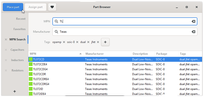
Placing Parts
You can then start placing parts by clicking the “Place Part” button in the top bar, or by simply typing p p (remember it as “Place Part”). This opens the Part Browser, where you can search your whole pool for the Parts you need and place them on the schematic.
Connecting Parts
Once you placed parts you can activate the “Draw net line” tool by typing n and drawing the connections. You can also simply drag out a pin and beginn connecting pins:
Basic Movement
You can move parts and nets by selecting them and typing m or by using the ←/↑/↓/→ arrow keys. Rotate with r and mirror with e
If you forget any of these keys, just press Spacebar to open the Spacebar Menu and search for the command you are looking for.
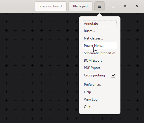
Power Nets
Because Circuits make much more sense if you use power nets you can create new power nets by clicking on the entry in the application menu:
In the window that pops up press the “Add power net” button, give the net a name and select a symbol style.
Place power nets with the “Place power symbol” Tool (type p o).
Annotation
Run the Annotation Tool to give all un-annotated parts (signified by the “?” in their reference designator) a propper number. So we go from this:
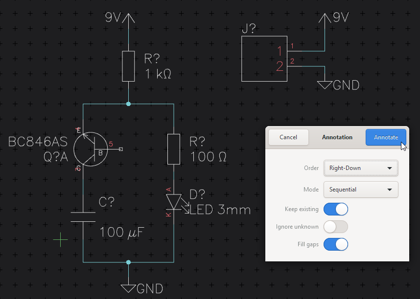
to this:
Once you are done, click on “Save” so you can start to layout the schematic you just created.
Next: Create a Board